media wiki for wiring diagram schematic, diy do it your self tutorial etc
Home
› Wiring Diagram Switch To Light Fixture / How Do I Connect A Light To A Switch When The Light Receives Power First Home Improvement Stack Exchange - The diagrams below show the various options.
Wiring Diagram Switch To Light Fixture / How Do I Connect A Light To A Switch When The Light Receives Power First Home Improvement Stack Exchange - The diagrams below show the various options.
Wiring Diagram Switch To Light Fixture / How Do I Connect A Light To A Switch When The Light Receives Power First Home Improvement Stack Exchange - The diagrams below show the various options.. This diagram illustrates wiring for one switch to control 2 or more lights. The power source is coming to light fitting first. The power source comes from the fixture and then connects to the power terminal. Electricians call the continuous hot wire the line wire. A 2 way switch wiring diagram with power feed from the switch light :
In this diagram, a new switch and light are added to an already existing light switch. The diagrams below show the various options. The hot and neutral terminals on each fixture are spliced with a pigtail to the circuit wires which then continue on to the next light. The electricity source and light fixture are connected to the same switch. The power source is coming to light fitting first.
Handyman Usa Wiring A 3 Way Or 4 Way Switch from www.handymanusa.com Ground connection diagram is shown separately. The power source is coming to a light switch first. In this diagram, power enters the fixture box. From there, 3 wire cables (black, white and red) are used between the switches, with a final 2 wire cable going from the last switch to the light fixture. You will see that there is a hot wire that is then spliced through a switch and that then goes to the hot terminal of the light. In this diagram, a new switch and light are added to an already existing light switch. The power source is coming to light fitting first. The hot and neutral terminals on each fixture are spliced with a pigtail to the circuit wires which then continue on to the next light.
You will see that there is a hot wire that is then spliced through a switch and that then goes to the hot terminal of the light.
This diagram illustrates wiring for one switch to control 2 or more lights. In this diagram, a new switch and light are added to an already existing light switch. The power source is coming to a light switch first. The hot and neutral terminals on each fixture are spliced with a pigtail to the circuit wires which then continue on to the next light. In this diagram, power enters the fixture box. The diagrams below show the various options. You will see that there is a hot wire that is then spliced through a switch and that then goes to the hot terminal of the light. A 2 way switch wiring diagram with power feed from the switch light : The power source is coming to light fitting first. The white neutral wires are connected together in each switch box. Electrical outlet boxes can have numerous nm cables going in and out. The power source comes from the fixture and then connects to the power terminal. Diagrams shown on this page are simplified for clarity.
Electricians call the continuous hot wire the line wire. In this diagram, a new switch and light are added to an already existing light switch. The hot and neutral terminals on each fixture are spliced with a pigtail to the circuit wires which then continue on to the next light. Ground connection diagram is shown separately. Wiring diagram for a new switch and light.
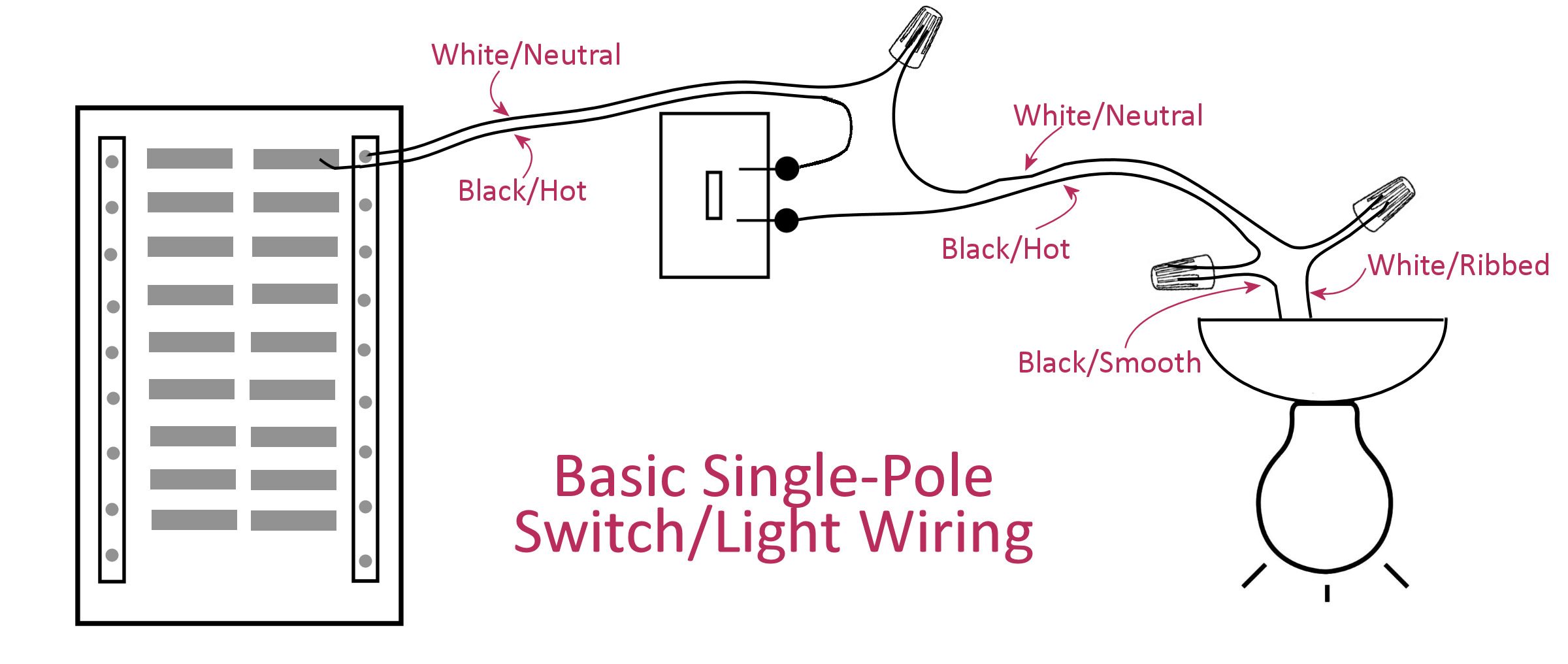
Electrical Basics Wiring A Basic Single Pole Light Switch Addicted 2 Decorating from www.addicted2decorating.com The black hot wire connects to the far right switch's common terminal. The electricity source and light fixture are connected to the same switch. The white neutral wires are connected together in each switch box. In this diagram, a new switch and light are added to an already existing light switch. Diagrams shown on this page are simplified for clarity. The diagrams below show the various options. From there, 3 wire cables (black, white and red) are used between the switches, with a final 2 wire cable going from the last switch to the light fixture. In this diagram, power enters the fixture box.
Electricians call the continuous hot wire the line wire.
The diagrams below show the various options. The power source is coming to light fitting first. This diagram illustrates wiring for one switch to control 2 or more lights. From there, 3 wire cables (black, white and red) are used between the switches, with a final 2 wire cable going from the last switch to the light fixture. The electricity source and light fixture are connected to the same switch. Electricians call the continuous hot wire the line wire. The power source comes from the fixture and then connects to the power terminal. In this diagram, power enters the fixture box. Diagrams shown on this page are simplified for clarity. You will see that there is a hot wire that is then spliced through a switch and that then goes to the hot terminal of the light. The power source is coming to a light switch first. The white neutral wires are connected together in each switch box. Ground connection diagram is shown separately.
In this diagram, power enters the fixture box. The diagrams below show the various options. The power source is coming to a light switch first. The hot and neutral terminals on each fixture are spliced with a pigtail to the circuit wires which then continue on to the next light. Ground connection diagram is shown separately.
Light Ceiling Fans Latching Relay Electrical Switches Wiring Diagram Wires Light Fixture Angle Text Png Pngwing from w7.pngwing.com The white neutral wires are connected together in each switch box. You will see that there is a hot wire that is then spliced through a switch and that then goes to the hot terminal of the light. The hot and neutral terminals on each fixture are spliced with a pigtail to the circuit wires which then continue on to the next light. Wiring diagram for a new switch and light. This diagram illustrates wiring for one switch to control 2 or more lights. Ground connection diagram is shown separately. From there, 3 wire cables (black, white and red) are used between the switches, with a final 2 wire cable going from the last switch to the light fixture. See actual switch box wiring.
In this diagram, a new switch and light are added to an already existing light switch.
You will see that there is a hot wire that is then spliced through a switch and that then goes to the hot terminal of the light. The white neutral wires are connected together in each switch box. In this diagram, power enters the fixture box. The power source is coming to light fitting first. The black hot wire connects to the far right switch's common terminal. From there, 3 wire cables (black, white and red) are used between the switches, with a final 2 wire cable going from the last switch to the light fixture. Ground connection diagram is shown separately. Electrical outlet boxes can have numerous nm cables going in and out. The power source comes from the fixture and then connects to the power terminal. The hot and neutral terminals on each fixture are spliced with a pigtail to the circuit wires which then continue on to the next light. See actual switch box wiring. The diagrams below show the various options. Diagrams shown on this page are simplified for clarity.