media wiki for wiring diagram schematic, diy do it your self tutorial etc
Home
› Wiring Diagram For Trailer Lights And Brakes / 7 Pin Trailer Brake Wiring Diagram | Trailer Wiring Diagram - As mentioned above, there are a number of the following diagrams and bullet points provide the australian standard for 5 and 7 pin plugs and knowing these colour codes can save you the time consuming exercise of testing lights by means of.
Wiring Diagram For Trailer Lights And Brakes / 7 Pin Trailer Brake Wiring Diagram | Trailer Wiring Diagram - As mentioned above, there are a number of the following diagrams and bullet points provide the australian standard for 5 and 7 pin plugs and knowing these colour codes can save you the time consuming exercise of testing lights by means of.
Wiring Diagram For Trailer Lights And Brakes / 7 Pin Trailer Brake Wiring Diagram | Trailer Wiring Diagram - As mentioned above, there are a number of the following diagrams and bullet points provide the australian standard for 5 and 7 pin plugs and knowing these colour codes can save you the time consuming exercise of testing lights by means of.. Installing a trailer light wiring kit and brake controller in my 1999 toyota 4runner. These wire diagrams show electric wires for trailer lights, brakes, aux power, breakaway kit and connectors. Wiring a boat trailer for brakes and lights. Wiring diagram for utility trailer with electric brakes building tiny house on flatbed trailer and need brake wiring a boat trailer for brakes and lights ** if requested.we can still use a 5 wire round plug.
Trailer brake light wiring diagram nice trailer brake. Many trailers have three circuits. Horse trailer electrical wiring diagrams. Trailer lights and wiring harness nissan titan forum. The diagram below is not intended to be a wiring diagram per.
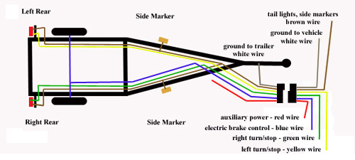
Wiring A Boat Trailer For Brakes And Lights from www.my-inflatable-boat.com 4 way flat molded round 1 1/4″ diameter metal connector allows 1 or 2 additional wiring and lighting functions such as back up lights, auxiliary 12v power or electric brakes. 10 7 pin trailer wiring harness motor within connector. Bunk glide on assembly instructions. The circuits are for left and right brake lights and running lights. Ebs (electronic brake system) connectors are used for the electrical connection of the abs/ebs braking systems between the truck and trailer for both 12v and 24v electrical systems. Look for a crossover cable color code with a wiring diagram for rj45 crossover cable or cross cable is a type of ethernet cable that i. Blue pin for electric brakes. Wiring diagram for electric trailer brake controller.
Blue pin for electric brakes.
Are now using 5 wire flat plug wiring to be more compatible with 4 and 5 wire vehicles. All new ck trailer tow wiring diagram png. 1999 ford f250 tail light wiring diagram. Ebs (electronic brake system) connectors are used for the electrical connection of the abs/ebs braking systems between the truck and trailer for both 12v and 24v electrical systems. Wiring a boat trailer for brakes and lights. Three wires are for the trailer while the last wire is the ground wire. Learning trailer wiring diagram better. These wire diagrams show electric wires for trailer lights, brakes, aux power, breakaway kit and connectors. Bunk glide on assembly instructions. 5 way trailer wiring diagram allows basic hookup of the trailer and allows using 3 main lighting functions and 1 extra function that depends on brake lights; Example wiring diagram for multiple battery cutoff switches. Some trailer builders just connect this wire to the frame, then connect the. The following diagram conforms to the standard agreed upon by vehicle manufacturers and companies producing the trailer in addition to the above some cars and trucks have a separate light for the brake light, most commonly identified by amber turn lenses in the rear.
Bunk glide on assembly instructions. Tail light converters brake control wiring vehicles towed behind a motorhome wiring diagram for common plugs breakaway switches. The diagram below is not intended to be a wiring diagram per. Trailer wiring diagram 5 wire vivresaville. Horse trailer electrical wiring diagrams.
Trailer Wire Harness Diagrams Brakes | Trailer Wiring Diagram from trailer-wiring-diagram.com Installing a trailer light wiring kit and brake controller in my 1999 toyota 4runner. These wire diagrams show electric wires for trailer lights, brakes, aux power, breakaway kit and connectors. Now tape the trailer wiring together is about 16 spacing, this just helps keep everything organized and makes it easier to insert in the split casing. Horse trailer electrical wiring diagrams. Foot operated dimmer switch wiring diagram headlight. Karavan boat trailer wiring diagram. Need a trailer wiring diagram? The industry standard found on trailers is a common bulb system.
Many trailers have three circuits.
Bunk glide on assembly instructions. Usually, there are three types of diagrams people can take a look at when aiming to assemble cables for trailers. Wiring diagram for utility trailer with electric brakes building tiny house on flatbed trailer and need brake wiring a boat trailer for brakes and lights The industry standard found on trailers is a common bulb system. As mentioned above, there are a number of the following diagrams and bullet points provide the australian standard for 5 and 7 pin plugs and knowing these colour codes can save you the time consuming exercise of testing lights by means of. The circuits are for left and right brake lights and running lights. Trailer wiring diagram for 6 pin & 7 pin conductor plugs q. The following diagram is a general guide for wiring common brake controllers into cars. Trailer lights and wiring harness nissan titan forum. Red 12 volt auxiliary power. 1999 ford f250 tail light wiring diagram. Three wires are for the trailer while the last wire is the ground wire. The industry standard for trailer tail lights is an 1157″ bulb, which is installed by pushing into the light socket and twisting it so that both looking at a diagram each side should be independent from the connector split back.
Special light and wiring systems need to be installed on your tow vehicle before you can tow any trailer. 4 way flat molded round 1 1/4″ diameter metal connector allows 1 or 2 additional wiring and lighting functions such as back up lights, auxiliary 12v power or electric brakes. Color coding is not standard among all manufacturers. Blue pin for electric brakes. Identify the wires on your vehicle and trailer by function only.
Electric Trailer Brake Wiring Schematic | Free Wiring Diagram from ricardolevinsmorales.com Installing a trailer light wiring kit and brake controller in my 1999 toyota 4runner. 4 way flat molded round 1 1/4″ diameter metal connector allows 1 or 2 additional wiring and lighting functions such as back up lights, auxiliary 12v power or electric brakes. Trailer lights and wiring harness nissan titan forum. The industry standard for trailer tail lights is an 1157″ bulb, which is installed by pushing into the light socket and twisting it so that both looking at a diagram each side should be independent from the connector split back. All new ck trailer tow wiring diagram png. Some trailer builders just connect this wire to the frame, then connect the. Wiring diagram for trailer lights and because the lights perform? Since the receptacle outlet performs?
Green pin yellow pin for right brake light and turn markers.
Many trailers have three circuits. Ebs (electronic brake system) connectors are used for the electrical connection of the abs/ebs braking systems between the truck and trailer for both 12v and 24v electrical systems. 2007 20ft sea ray 200 sundeck share this 25. ** if requested.we can still use a 5 wire round plug. Now tape the trailer wiring together is about 16 spacing, this just helps keep everything organized and makes it easier to insert in the split casing. Foot operated dimmer switch wiring diagram headlight. Turn signals and brake lights should be the brighter illumination and. 4 way flat molded round 1 1/4″ diameter metal connector allows 1 or 2 additional wiring and lighting functions such as back up lights, auxiliary 12v power or electric brakes. The industry standard found on trailers is a common bulb system. The wiring schematic that we use is: Green pin yellow pin for right brake light and turn markers. Horse trailer electrical wiring diagrams. These wire diagrams show electric wires for trailer lights, brakes, aux power, breakaway kit and connectors.