media wiki for wiring diagram schematic, diy do it your self tutorial etc
Home
› What Is A Wiring Schematic - What Is An Electrical Diagram And What Are The Different Types Of Electrical Diagrams Instrumentation And Control Engineering - Wiring diagrams are often used for troubleshooting electrical malfunctions.
What Is A Wiring Schematic - What Is An Electrical Diagram And What Are The Different Types Of Electrical Diagrams Instrumentation And Control Engineering - Wiring diagrams are often used for troubleshooting electrical malfunctions.
What Is A Wiring Schematic - What Is An Electrical Diagram And What Are The Different Types Of Electrical Diagrams Instrumentation And Control Engineering - Wiring diagrams are often used for troubleshooting electrical malfunctions.. Six wire three phase electric motors are dual voltage motors. An example of a wiring diagram for a motor controller is shown in figure 1. Allowable wire and cable types and sizes are specified according to the circuit operating voltage and electric current capability, with further restrictions on the. Three phase wiring diagrams always use wiring diagram supplied on motor nameplate. A wiring diagram is a simplified traditional pictorial depiction of an electrical circuit.
Information for boats built before not available. Wiring diagrams wiring diagrams, or layouts, illustrate the physical connections, or wiring, between components. Use the legend to understand what each symbol on the circuit means. When and how to use a wiring diagram It reveals the components of the circuit as simplified shapes, and also the power and signal connections in between the tools.
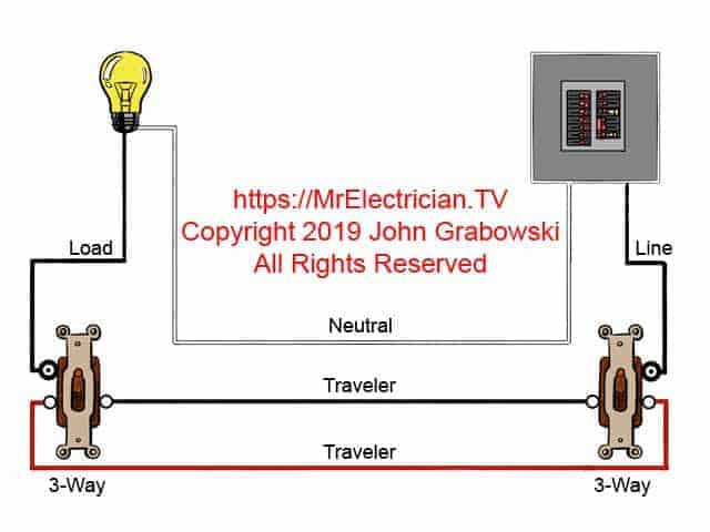
Three Way Switch Wiring Diagrams from mrelectrician.tv The power supply is shown at the top and the earth at the bottom to facilitate understanding of the current flow. What is a wiring diagram? If you're looking for a new trailer, check out our inventory now. Above we have describes the main types of trailer wiring diagrams. For example, how the horns are powered and connected to the controller on your steering wheel. Let's have a look at their differences with the help of a table. Wiring diagrams wiring diagrams, or layouts, illustrate the physical connections, or wiring, between components. In this case, you will need a set of wiring taps and a pair of pliers.
Allowable wire and cable types and sizes are specified according to the circuit operating voltage and electric current capability, with further restrictions on the.
Note that symbols are discussed in detail later). In part 1 of this series, you've learned how to read and understand a wiring diagram of an. Edraw wiringplan is a wiring diagram software that is designed to help engineers and technician make accurate and useful diagrams of a wiring project. When and how to use a wiring diagram That particular schematic focusses on the tone pot/volume pot relationship. Wiring diagrams wiring diagrams, or layouts, illustrate the physical connections, or wiring, between components. As with the volume pot, there are two ways of wiring up the tone pot. Automotive wiring basic symbols common symbols for automotive diagrams. Information for boats built before not available. What is a schematic diagram? Automotive electrical diagrams provide symbols that represent circuit component functions. Use the legend to understand what each symbol on the circuit means. Electrical wiring is an electrical installation of cabling and associated devices such as switches, distribution boards, sockets, and light fittings in a structure.
That said, for specific situations, there are industrial standards with different connectors and wire arrangements. A proper wiring diagram will be labeled and show connections in a way that prevents confusion about how connections are made. An example of a wiring diagram for a motor controller is shown in figure 1. Be very careful in wiring methods and workmanship. Wiring diagrams can be helpful in many ways, including illustrated wire colors, showing where different elements of your project go using electrical symbols, and showing what wire goes where.
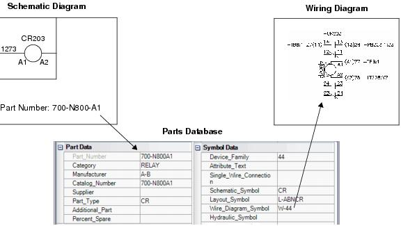
Wiring Diagrams Overview from docs.bentley.com We suggest this because it is difficult to diagnose your wiring issue over the phone or via chat. To connect the electric system of your trailer to the vehicle, you will be using special connector. That particular schematic focusses on the tone pot/volume pot relationship. Information for boats built before not available. As with the volume pot, there are two ways of wiring up the tone pot. We recommend these standards because they are pretty universal. Wiring diagram a wiring diagram is sometimes helpful to illustrate how a schematic can be realized in a prototype or production environment. Let's have a look at their differences with the help of a table.
Illustrated wiring diagrams for home electrical projects.
That said, for specific situations, there are industrial standards with different connectors and wire arrangements. Allowable wire and cable types and sizes are specified according to the circuit operating voltage and electric current capability, with further restrictions on the. This system uses 3 phase ac power (l1, l2 and l3) connected to the terminals. This pictorial diagram shows us the physical links that are far easy to understand an electrical circuit or system. It reveals the components of the circuit as simplified shapes, and also the power and signal connections in between the tools. Dashed lines indicate a single purchased component. Aj's truck and trailer center inc. Schematic diagrams are electrical layouts that mainly focus on the basic plan and function rather than its physical location. It shows how the electrical wires are interconnected and can also show where fixtures and components may be connected to the system. Wiring diagrams can be helpful in many ways, including illustrated wire colors, showing where different elements of your project go using electrical symbols, and showing what wire goes where. Let's have a look at their differences with the help of a table. Check for short circuits as you go, before the booster is connected. For example, a few basic symbols common to electrical schematics are shown as:
Above we have describes the main types of trailer wiring diagrams. Basically, the value of a schematic component calls out its most important characteristic. We suggest this because it is difficult to diagnose your wiring issue over the phone or via chat. When and how to use a wiring diagram It shows the components of the circuit as simplified shapes, and the power and signal connections between the devices.
Wiring Diagram Everything You Need To Know About Wiring Diagram from www.smartdraw.com Automotive electrical diagrams provide symbols that represent circuit component functions. Wiring diagrams wiring diagrams, or layouts, illustrate the physical connections, or wiring, between components. Illustrated wiring diagrams for home electrical projects. Basically, the value of a schematic component calls out its most important characteristic. Wiring diagram a wiring diagram is sometimes helpful to illustrate how a schematic can be realized in a prototype or production environment. I'm not talking about the entire filter (there are more ways that lead to rome!) but how the two are connected. Be very careful in wiring methods and workmanship. In this case, you will need a set of wiring taps and a pair of pliers.
A wiring diagram may include the wirings of a vehicle.
A wiring diagram may include the wirings of a vehicle. Be very careful in wiring methods and workmanship. Wiring diagram a wiring diagram is sometimes helpful to illustrate how a schematic can be realized in a prototype or production environment. Aj's truck and trailer center inc. In part 1 of this series, you've learned how to read and understand a wiring diagram of an. For example, how the horns are powered and connected to the controller on your steering wheel. One wiring diagram can signify all the interconnections, thereby signaling the relative locations. A schematic diagram is a picture that represents the components of a process, device, or other object using abstract, often standardized symbols and lines. Furthermore, wiring diagrams typically identify each component within a system by its part number and its serial number, including any changes that were made during the production run of an aircraft. The following trailer wiring diagram(s) and explanations are a cross between an electrical schematic and wiring on a trailer. Wiring diagrams are often used for troubleshooting electrical malfunctions. A wiring diagram is a simplified traditional pictorial depiction of an electrical circuit. It shows how the electrical wires are interconnected and can also show where fixtures and components may be connected to the system.